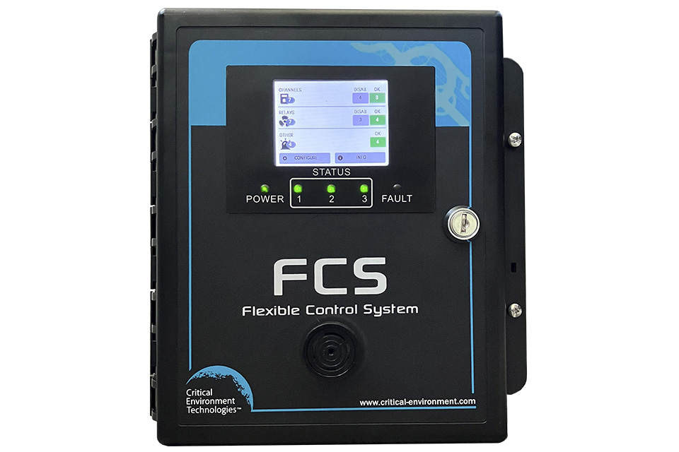
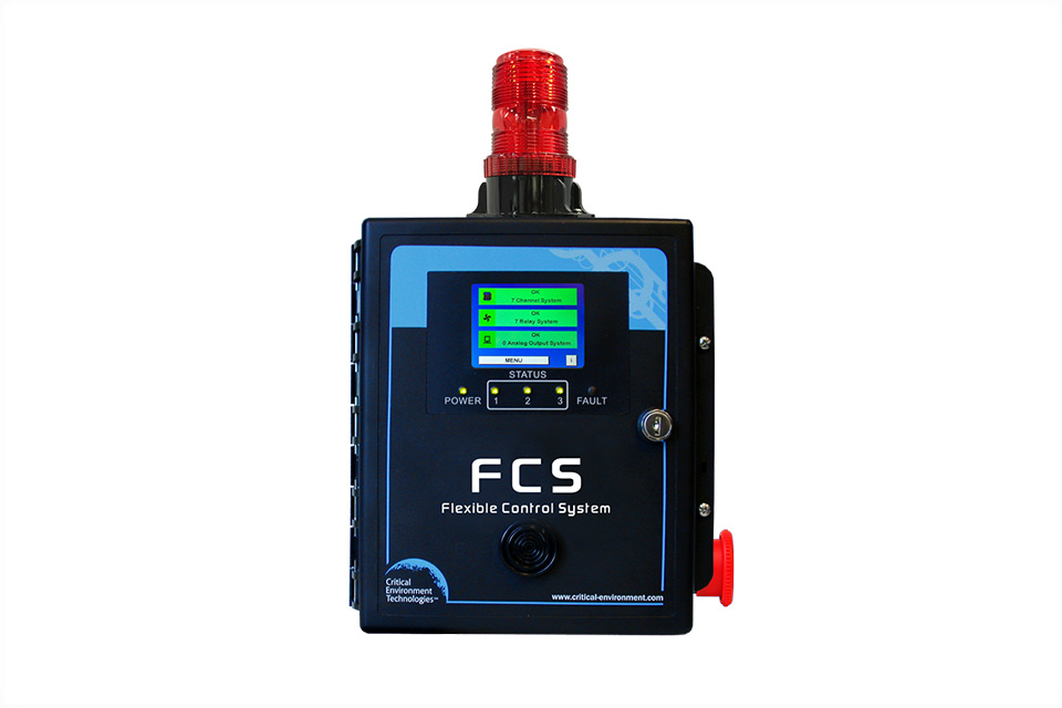
FCS Multi Channel System Controllers
High performance controller with logic and priority settings for monitoring toxic, combustible and refrigerant gases with versatile control functionality. Available with Modbus® or BACnet® communication with BAS, supports 4-20 mA and Modbus® driven VFDs.
- Available in 4 channels, 8 channels, 32 channels and 128 channels
- FCS-M models offer Modbus® RTU RS-485 digital output signal for LAN and WAN communications
- FCS-B models offer BACnet® MS/TP RS-485 output signal for WAN communications (for communicating with a BAS)
- Graphic, full colour, touchpad LCD screen with LED indicators
Description
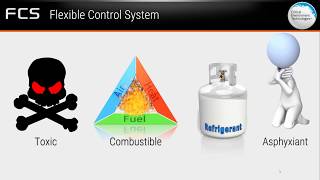
The FCS Flexible Control System is a sophisticated, high performance controller that offers multi-channel configurations for monitoring toxic, combustible and refrigerant gases with versatile control functionality for non-hazardous, non-explosion rated, commercial and light industrial applications. The FCS is designed to accept inputs from digital and/or analog transmitters and/or Peripheral Devices (in various combinations), using Modbus® RTU RS-485 or 4-20 mA analog input.
The FCS is available in 4 channel, 8 channel, 32 channel and 128 channel models with either Modbus® RTU RS-485 WAN output or with BACnet® MS/TP RS-485 WAN output for communicating with a Building Automation System (BAS).
All models include, four internal SPDT dry contact relays with field configurable time delays and trigger levels, a full colour LCD resistive touch screen with LED panel indicating configurable channel alarm status, relay status and fault conditions, intuitive menu system with password protection, enhanced logic control, priorities/zoning capabilities, a USB port for firmware upgrades, data logging and a door-mounted, audible alarm. The FCS has flexible configuration settings for analog outputs and supports 4-20 mA and Modbus® driven VFDs.
Optional value added features include, analog inputs and/or analog outputs, a top mounted strobe, a locking door, a manual shut off switch and a water tight, door-mounted audible alarm.
The FCS can be connected to the following CET remote devices:
- Remote strobe/horns
- Remote Display Module (CET-RDM)
- Remote Relay Module (RLY-4 and/or RLY-8)
- LNK-AI Analog Input device
- LNK-AO Analog Output device
- LNK-XT Network Extender
- Remote Power Supply (RPS-24VDC)
Features, Options and Remote Devices Guidelines
All models can be configured to comply with California Title-24 Building Energy Efficiency Standards. Specification details need to be given at time of order and additional settings can be implemented in the field as required.
Specifications
Mechanical
| Enclosure | ABS / Polycarbonate, IP54 rating with door mounted, water tight buzzer installed |
| Weight | 1.8 kg / 4 lbs |
| Size | 254 x 226 x 113 mm / 10.0 x 8.9 x 4.44 in |
User Interface
| Display | 8.1 cm (3.2") graphic, 1/4 VGA full colour resistive touch LCD screen with LED indicators for "POWER", "STATUS 1, 2 and 3" and "FAULT" |
Input/Output
| Input | Modbus® RTU RS-485 input 4-20 mA analog input (optional) |
| Output | Modbus® RTU RS-485 output to networked devices Modbus® RTU RS-485 output to BAS or DDC (FCS-M models) BACnet MS/TP RS-485 output to BAS or DDC (FCS-B models) 2 outputs drives for strobe/horn, 0.5 A @ 24 VDC max Field configurable 4-20 mA or 0-10 volts analog output (optional) |
| Relays | 4 internal SPDT dry contact relays, 5 A @ 240 VAC (up to 64 total with Remote Relay Modules) |
| Audible Alarm | Standard loud, door mounted buzzer, 90 dB @ 30 cm (1 ft) Optional: door mounted, water tight buzzer, 85 dB @ 60.96 cm (2 ft) |
| Top Mounted Strobe | Optional: bright, red, top mounted strobe, 10 - 30 VDC, 13 cm H x 6.1 cm dia / 5.2 inches H x 2.4 inches dia |
Electrical
| Power Requirement | Line Voltage: 90 – 240 VAC, 50 -60 Hz, 75 W |
| Current Draw | Line Voltage (110 VAC): approx. 1.0 amps Line Voltage (220 VAC): approx. 0.5 amps |
| Power Distribution | Total power available for Remote & Peripheral Devices and Options 65 W @ 24 VDC |
| Wiring | Line Voltage: VAC 3-conductor (Line, Neutral, Ground) shielded, stranded 16 - 18 AWG within conduit LAN Modbus® RTU RS-485 4-conductor, 18 - 22 AWG twisted, shielded, stranded WAN (output to BAS) Modbus® RTU (version 1.1b3) RS-485 or BACnet® MS/TP (version 1 rev 14) RS-485 4-conductor, 18 - 22 AWG twisted, shielded, stranded |
| Fuses | Thermal, resetting |
Environmental
| Operating Temperature | -20°C to 40°C (-4°F to 104°F) with internal heater -40°C to -40°C (-40°F to 104°F) |
| Operating Humidity | 15 - 90% RH non-condensing |
Certifications
| Conforms to: | CSA-C22.2 No. 205-12, UL508 (Edition 17):2007 EMC Directive 2004/108/EC, EN 50270:2006, Type 1, EN61010 FCC. This device complies with part 15 of the FCC Rules. Operation is subject to the following two conditions: (1) This device may not cause harmful interference, and (2) this device must accept any interference received, including interference that may cause undesired operation. FCS-B, FCS-B-X models are Listed by BTL (where X represents one or more factory installed Options) RoHS compliant circuit boards |
Applications
Detected Gases
Documents
Application: AI Workload Zones & Tower Stacks - FCS and CGAS-D-IR
PDF • 3.8 MB • Application Guides
Application: Brewery - FCS and CGAS
PDF • 746 KB • Application Guides
Application: Chiller Rooms - FCS and CGAS IR
PDF • 933 KB • Application Guides
Application: Cold Storage / Freezer Rooms - FCS and CGAS
PDF • 602 KB • Application Guides
Application: Distribution Warehouse - FCS and CGAS Detector
PDF • 908 KB • Application Guides
Application: Enclosed Parking - FCS and CGAS-D
PDF • 669 KB • Application Guides
Application: Greenhouse Production - FCS and CGAS-D CO2 CO & CH4
PDF • 2.3 MB • Application Guides
Application: Hotels - FCS and CGAS IR
PDF • 503 KB • Application Guides
Application: Ice Arenas - FCS, CGAS and CXT2
PDF • 1020 KB • Application Guides
Application: Indoor Swimming Pools - FCS and CGAS CL2 O3
PDF • 942 KB • Application Guides
Application: Oil Extraction - FCS and CXT2
PDF • 2.0 MB • Application Guides
Application: Refrigerant Shafts - FCS and CGAS-D-IR
PDF • 750 KB • Application Guides
Application: Schools - FCS and CGAS Public Space
PDF • 659 KB • Application Guides
Application: Waste Water Treatment Plant - FCS, CGAS and CXT2
PDF • 960 KB • Application Guides
Application: Winery - FCS and CGAS
PDF • 879 KB • Application Guides
FCS-4 Brochure
PDF • 3.3 MB • Brochures
BTL Listing (PICS) for BACnet Module for FCS-B
PDF • 212 KB • Certifications
Controls Schematic: Distilleries - Central Panel
DWG • 1.3 MB • Controls Schematics
Controls Schematic: Distilleries - Central Panel
PDF • 1.4 MB • Controls Schematics
Controls Schematic: Distilleries - Standalone Units
PDF • 379 KB • Controls Schematics
Controls Schematic: Distilleries - Standalone Units
DWG • 1.1 MB • Controls Schematics
Controls Schematic: Refrigeration System - Central Panel
DWG • 1.3 MB • Controls Schematics
Controls Schematic: Refrigeration System - Central Panel
PDF • 801 KB • Controls Schematics
Controls Schematic: Refrigeration System - Standalone Units
DWG • 1.1 MB • Controls Schematics
Controls Schematic: Refrigeration System - Standalone Units
PDF • 402 KB • Controls Schematics
Controls Schematic: Vehicle Exhaust - Central Panel
PDF • 624 KB • Controls Schematics
Controls Schematic: Vehicle Exhaust - Central Panel
DWG • 798 KB • Controls Schematics
Controls Schematic: Vehicle Exhaust - Standalone Units
DWG • 981 KB • Controls Schematics
Controls Schematic: Vehicle Exhaust - Standalone Units
PDF • 331 KB • Controls Schematics
Controls Schematic: Warehouse - Central Panel
DWG • 803 KB • Controls Schematics
Controls Schematic: Warehouse - Central Panel
PDF • 619 KB • Controls Schematics
Controls Schematic: Warehouse - Standalone Units
DWG • 1.1 MB • Controls Schematics
Controls Schematic: Warehouse - Standalone Units
PDF • 397 KB • Controls Schematics
Controls Schematic: Welding Shop - Central Panel
DWG • 781 KB • Controls Schematics
Controls Schematic: Welding Shop - Central Panel
PDF • 549 KB • Controls Schematics
Controls Schematic: Welding Shop - Standalone Units
PDF • 415 KB • Controls Schematics
Controls Schematic: Welding Shop - Standalone Units
DWG • 1.1 MB • Controls Schematics
Controls Schematic: Wineries and Breweries - Central Panel
DWG • 791 KB • Controls Schematics
Controls Schematic: Wineries and Breweries - Central Panel
PDF • 692 KB • Controls Schematics
Controls Schematic: Wineries and Breweries - Standalone Units
PDF • 556 KB • Controls Schematics
Controls Schematic: Wineries and Breweries - Standalone Units
DWG • 1.1 MB • Controls Schematics
FCS Datasheet
PDF • 265 KB • Datasheets
FCS-32 Datasheet
PDF • 256 KB • Datasheets
FCS-4 Datasheet
PDF • 292 KB • Datasheets
FCS-8 Datasheet
PDF • 264 KB • Datasheets
Engineering Spec: California Title 24 - FCS and CGAS-D-CO-NO2
DOC • 411 KB • Engineering Specs
Engineering Spec: Methane Leaks - FCS-M and CXT2-A-ICH4
DOC • 403 KB • Engineering Specs
Engineering Spec: Refrigeration Machinery Room - FCS and CGAS-D-IR
DOCX • 384 KB • Engineering Specs
Engineering Spec: Vehicle Exhaust - FCS and CGAS-D-CO-NO2
DOCX • 382 KB • Engineering Specs
Gas Detection Schedule: Distilleries - Central Panel
PDF • 171 KB • Gas Detection Schedules
Gas Detection Schedule: Distilleries - Central Panel
XLSX • 22 KB • Gas Detection Schedules
Gas Detection Schedule: Distilleries - Central Panel
DWG • 59 KB • Gas Detection Schedules
Gas Detection Schedule: Distilleries - Standalone Units
PDF • 170 KB • Gas Detection Schedules
Gas Detection Schedule: Distilleries - Standalone Units
XLSX • 22 KB • Gas Detection Schedules
Gas Detection Schedule: Distilleries - Standalone Units
DWG • 60 KB • Gas Detection Schedules
Gas Detection Schedule: Refrigeration System - Central Panel
DWG • 63 KB • Gas Detection Schedules
Gas Detection Schedule: Refrigeration System - Central Panel
PDF • 171 KB • Gas Detection Schedules
Gas Detection Schedule: Refrigeration System - Central Panel
XLSX • 19 KB • Gas Detection Schedules
Gas Detection Schedule: Refrigeration System - Standalone Units
PDF • 169 KB • Gas Detection Schedules
Gas Detection Schedule: Refrigeration System - Standalone Units
XLSX • 18 KB • Gas Detection Schedules
Gas Detection Schedule: Refrigeration System - Standalone Units
DWG • 48 KB • Gas Detection Schedules
Gas Detection Schedule: Vehicle Exhaust - Central Panel
XLSX • 17 KB • Gas Detection Schedules
Gas Detection Schedule: Vehicle Exhaust - Central Panel
PDF • 172 KB • Gas Detection Schedules
Gas Detection Schedule: Vehicle Exhaust - Central Panel
DWG • 61 KB • Gas Detection Schedules
Gas Detection Schedule: Vehicle Exhaust - Standalone Units
XLSX • 19 KB • Gas Detection Schedules
Gas Detection Schedule: Vehicle Exhaust - Standalone Units
PDF • 170 KB • Gas Detection Schedules
Gas Detection Schedule: Vehicle Exhaust - Standalone Units
DWG • 53 KB • Gas Detection Schedules
Gas Detection Schedule: Warehouse - Central Panel
XLSX • 19 KB • Gas Detection Schedules
Gas Detection Schedule: Warehouse - Central Panel
PDF • 172 KB • Gas Detection Schedules
Gas Detection Schedule: Warehouse - Central Panel
DWG • 63 KB • Gas Detection Schedules
Gas Detection Schedule: Warehouse - Standalone Units
PDF • 172 KB • Gas Detection Schedules
Gas Detection Schedule: Warehouse - Standalone Units
XLSX • 19 KB • Gas Detection Schedules
Gas Detection Schedule: Warehouse - Standalone Units
DWG • 63 KB • Gas Detection Schedules
Gas Detection Schedule: Welding Shop - Central Panel
DWG • 64 KB • Gas Detection Schedules
Gas Detection Schedule: Welding Shop - Central Panel
PDF • 171 KB • Gas Detection Schedules
Gas Detection Schedule: Welding Shop - Central Panel
XLSX • 22 KB • Gas Detection Schedules
Gas Detection Schedule: Welding Shop - Standalone Units
XLSX • 22 KB • Gas Detection Schedules
Gas Detection Schedule: Welding Shop - Standalone Units
PDF • 171 KB • Gas Detection Schedules
Gas Detection Schedule: Welding Shop - Standalone Units
DWG • 66 KB • Gas Detection Schedules
Gas Detection Schedule: Wineries and Breweries - Central Panel
PDF • 171 KB • Gas Detection Schedules
Gas Detection Schedule: Wineries and Breweries - Central Panel
XLSX • 22 KB • Gas Detection Schedules
Gas Detection Schedule: Wineries and Breweries - Central Panel
DWG • 61 KB • Gas Detection Schedules
Gas Detection Schedule: Wineries and Breweries - Standalone Units
PDF • 170 KB • Gas Detection Schedules
Gas Detection Schedule: Wineries and Breweries - Standalone Units
DWG • 60 KB • Gas Detection Schedules
Gas Detection Schedule: Wineries and Breweries - Standalone Units
XLSX • 22 KB • Gas Detection Schedules
FCS Digital Network Installation Guidelines
PDF • 121 KB • Guidelines
FCS Digital Network Installation Checklist
PDF • 144 KB • Manuals
FCS Installation Manual - firmware v1.58 to v2.0
PDF • 7.4 MB • Manuals
FCS Installation Manual - firmware v2.2
PDF • 2.0 MB • Manuals
FCS Installation Manual - firmware v2.3 onwards
PDF • 1.9 MB • Manuals
FCS Operation Manual - firmware v1.58 to v2.0
PDF • 1.3 MB • Manuals
FCS Operation Manual - firmware v2.2 onwards
PDF • 1.2 MB • Manuals
FCS Operation Manual - up to firmware v1.58
PDF • 1.9 MB • Manuals
FCS Features Options and Remote Devices
PDF • 87 KB • Product Guides
FCS Product Overview Diagram
PDF • 745 KB • Product Guides
FCS System Diagram
PDF • 316 KB • Product Guides
Quick Reference Guide to Internal Analog Outputs in FCS Controller
PDF • 240 KB • Product Guides
Product Spec: FCS-32-B Controller
PDF • 159 KB • Product Specs
Product Spec: FCS-32-M Controller
PDF • 158 KB • Product Specs
Product Spec: FCS-4-B Controller
PDF • 159 KB • Product Specs
Product Spec: FCS-4-M Controller
PDF • 158 KB • Product Specs
Product Spec: FCS-8-B Controller
PDF • 159 KB • Product Specs
Product Spec: FCS-8-M Controller
PDF • 158 KB • Product Specs
Product Spec: FCS-B Controller
PDF • 159 KB • Product Specs
Product Spec: FCS-M Controller
PDF • 158 KB • Product Specs
ChillerSense Solution Guide
PDF • 2.7 MB • Compliance Guides
ParkSense Solution Guide
PDF • 2.7 MB • Compliance Guides
Wiring Diagram: FCS with LNK-AI
PDF • 128 KB • Wiring Diagrams
Wiring Diagram: FCS with RSL-120V G Flashing RAB Steady
PDF • 304 KB • Wiring Diagrams
Wiring Diagram: FCS with RSL-24V G Flashing RAB Steady
PDF • 292 KB • Wiring Diagrams
Wiring Diagram: FCS-32-B System Wiring
PDF • 803 KB • Wiring Diagrams
Wiring Diagram: FCS-32-B-L with CGAS-D-NH3
PDF • 872 KB • Wiring Diagrams
Wiring Diagram: FCS-32-M System Wiring
PDF • 790 KB • Wiring Diagrams
Wiring Diagram: FCS-32-M-L with CGAS-D-NH3
PDF • 862 KB • Wiring Diagrams
Wiring Diagram: FCS-4-B System Wiring
PDF • 915 KB • Wiring Diagrams
Wiring Diagram: FCS-4-M System Wiring
PDF • 903 KB • Wiring Diagrams
Wiring Diagram: FCS-8-B System Wiring
PDF • 982 KB • Wiring Diagrams
Wiring Diagram: FCS-8-M System Wiring
PDF • 971 KB • Wiring Diagrams
Wiring Diagram: FCS-8-M with CXT2-D
PDF • 971 KB • Wiring Diagrams
Wiring Diagram: FCS-B System Wiring
PDF • 803 KB • Wiring Diagrams
Wiring Diagram: FCS-B with CGAS-D and RPS-24VDC
PDF • 497 KB • Wiring Diagrams
Wiring Diagram: FCS-B with Option -AIAO and RDM
PDF • 298 KB • Wiring Diagrams
Wiring Diagram: FCS-B with Option AIAO and Remote Relay RLY-4
PDF • 489 KB • Wiring Diagrams
Wiring Diagram: FCS-M System Wiring
PDF • 790 KB • Wiring Diagrams
Wiring Diagram: FCS-M with CGAS-D and RLY-4
PDF • 487 KB • Wiring Diagrams
Wiring Diagram: FCS-M with CGAS-D and RSH-24V-R
PDF • 442 KB • Wiring Diagrams
Wiring Diagram: FCS-M with LNK-AO
PDF • 128 KB • Wiring Diagrams
Wiring Diagram: FCS-M with RDM
PDF • 286 KB • Wiring Diagrams
Wiring Diagram: FCS-M with RLY-8 connected to RSH-24V and exhaust fan
PDF • 235 KB • Wiring Diagrams
Wiring Diagram: LNK-XT Powered by Controller
PDF • 109 KB • Wiring Diagrams
Wiring Diagram: LNK-XT Powered by RPS-24VDC
PDF • 112 KB • Wiring Diagrams
Video Library
FCS Product Overview

ASK THE EXPERTS - Gas Detection System: How It Works

ASK THE EXPERTS - Gas Detection System: Your Design

ASK THE EXPERTS - Gas Detection System: FCS Models

ASK THE EXPERTS - Gas Detection Controller: FCS Relays

ASK THE EXPERTS - Gas Detection Controller: Adding Relays to the FCS

ASK THE EXPERTS - Gas Detection Controller: How Relays Work

ASK THE EXPERTS - Gas Detection Controller: FCS Highlighted Features

ASK THE EXPERTS - Gas Detection Controller: Configuring the FCS After Installation

ASK THE EXPERTS - Gas Detection System: Interaction with VFD Fans
Related Products
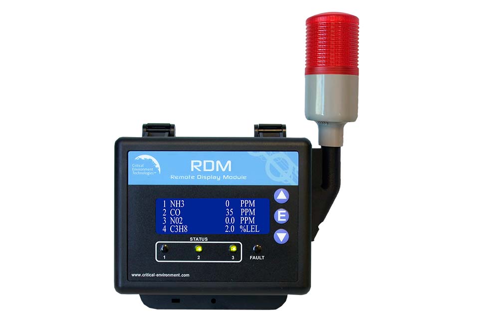
RDM Remote Display
Provides convenient viewing of gas level readings from a secondary location. Displays gas level readings, channel status and faults received from the FCS, offers configurable display settings.
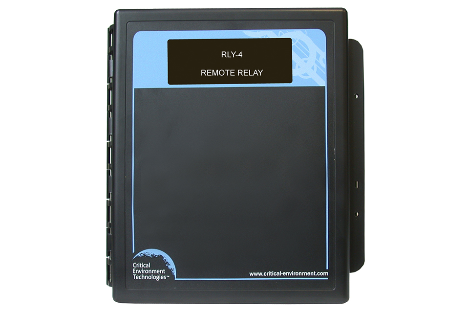
RLY-4 and RLY-8 Remote Relays
Provides an additional 4 or 8 physical relays to a fixed gas detection system plus an additional 2 or 4 horn/strobe drives.
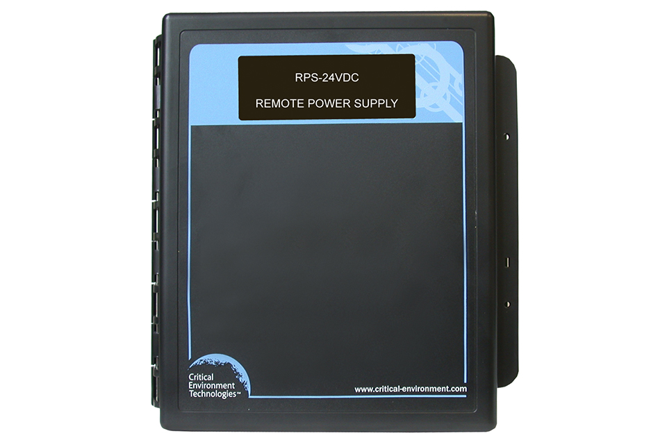
RPS-24VDC Remote Power Supply
Provides additional power to large networks. Converts 90 - 240 VAC power to 24 VDC power, providing a renewed amount of power to compensate for voltage drops in large fixed system applications and/or very long wire runs
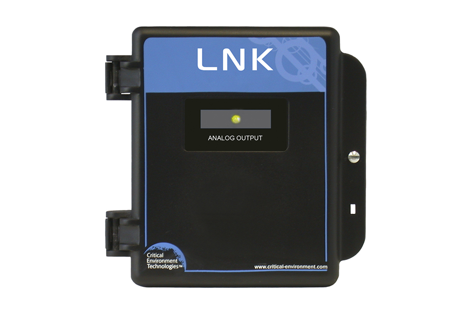
LNK-AO Analog Output Peripheral Device
Adds 4 additional analog outputs to a gas detection system. Adds four channels of 4 - 20 mA analog output to a Modbus® RS-485 network configured with one of the FCS Multi Channel System Controllers.

LNK-XT Network Extender Peripheral Device
Works as signal booster and allows a longer distance between devices. Ideal for large applications to create an efficient distribution network of specialized gas detection devices that can communicate over large distances.
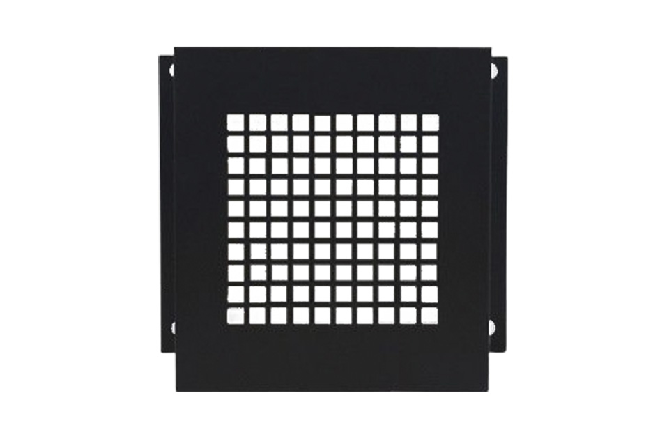
Metal Protective Guards
A heavy duty metal guard that is installed over the gas detector or controller. Helps protect the gas detection equipment against impact, abrasive damage, theft and vandalism.
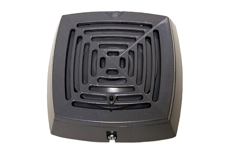
Remote Industrial Horn
Surface mount industrial horn with mounting bracket, available for indoor or outdoor use. A low-current, high decibel, surface mount, vibrating horn for heavy-duty indoor or outdoor use.
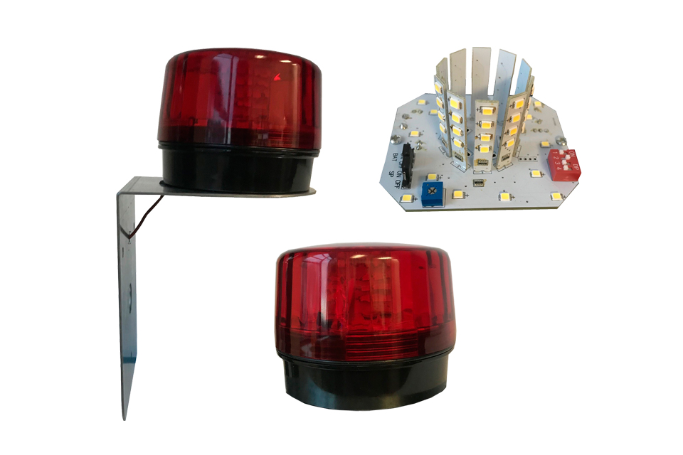
RSA-24V Remote LED Strobe Light
Bright visual alarm with multiple user selectable flash patterns. A remote LED strobe light with multiple user selectable flash patterns, comes with wall mounting bracket for easy installation.
Top Mounted Strobe (Option -L)
A high powered, red LED flashing beacon that is factory installed at time of order and offers excellent flash intensity, durable vibration resistant construction and a long life. 4 flash patterns, weather and corrosion resistant.
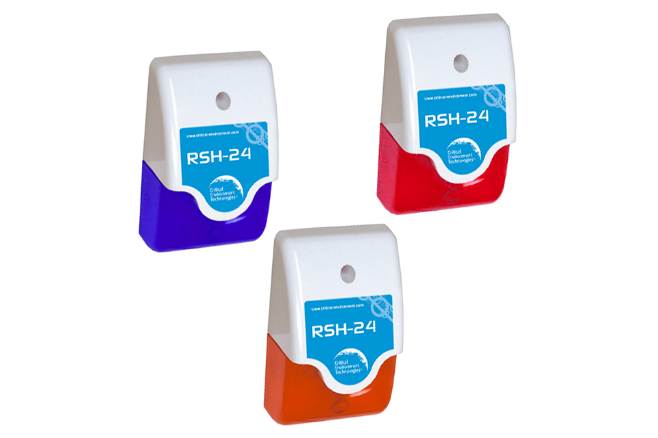
RSH-24V Remote Strobe & Horn
Two alarm features in one safety device, mounting fixture not included. Available in 3 different lens colours, combines a visual and an audible alarm feature into one compact, low profile device.
Manual Shutoff Switch (Option -SW)
An emergency stop, push button switch that allows a person to manually shutdown equipment in the event of an emergency. Ideal for refrigeration applications; when combined with the Top Mounted Strobe, the device meets B52 code requirements.
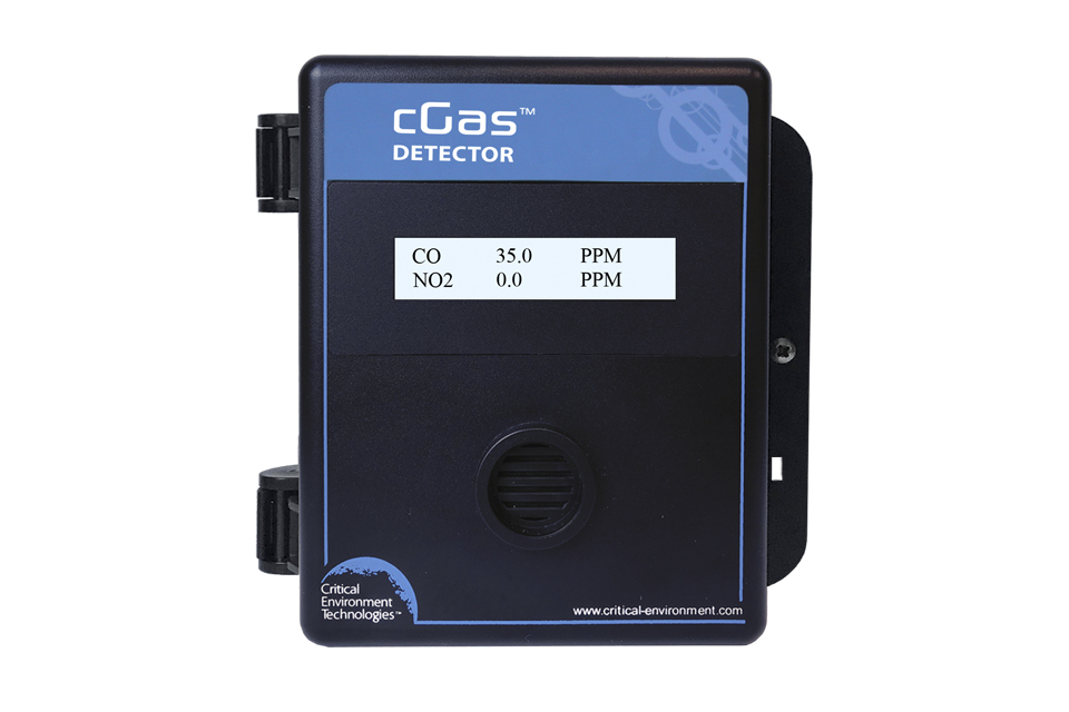
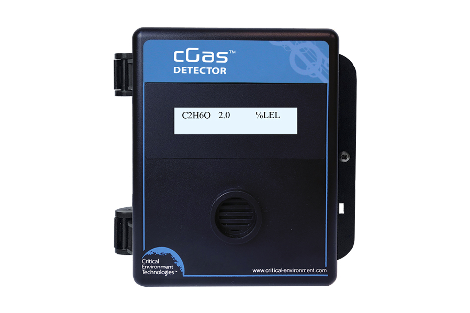
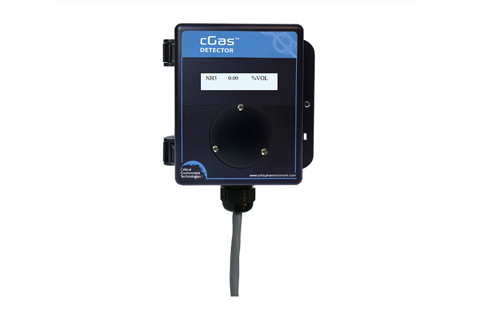
cGas Detector Digital Transmitter
One or two channel Modbus® or BACnet® gas detector with flexible customization options and Plug & Play Smart Sensor Technology.
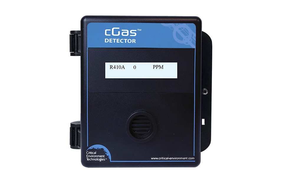
cGas Detector Analog Transmitter
Single channel, analog gas detector with Plug & Play Smart Sensor Technology.
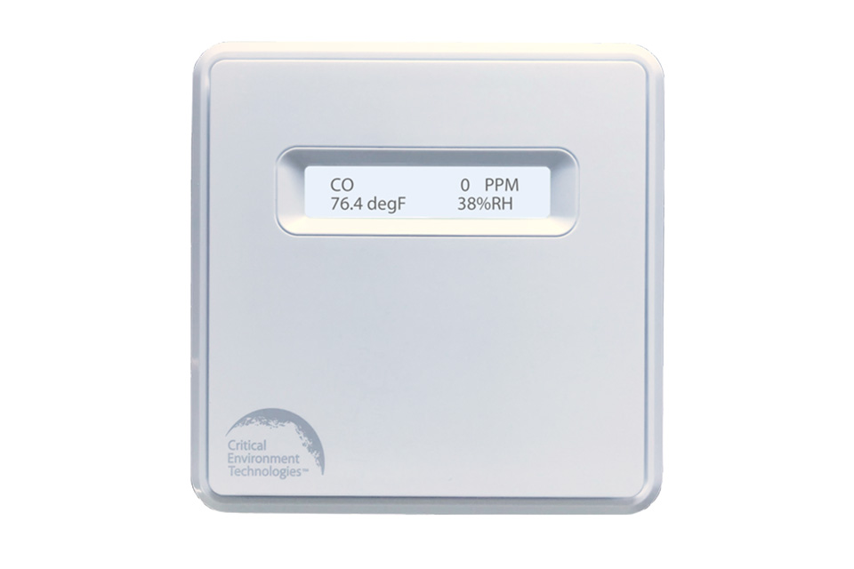
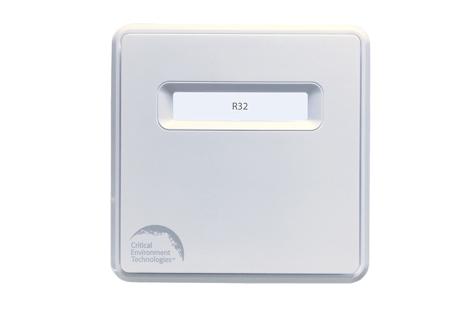
cGas Detector for Indoor Public Spaces
Single channel gas detector with an aesthetically pleasing design to reduce noticeability when used in publicly occupied spaces such as hotels and schools.
cGas Detector IR Refrigerant Transmitter
Non-dispersive infrared refrigerant gas detector with accurate, low level leak detection, available with analog output or BACnet® or Modbus® output and Plug & Play Smart Sensor Technology.
cGas Detector VRF IR Refrigerant Transmitter
An aesthetic, non-dispersive infrared refrigerant gas detector for acute leak detection in modern energy-efficient buildings utilizing Variable Refrigerant Flow (VRF) HVAC systems.
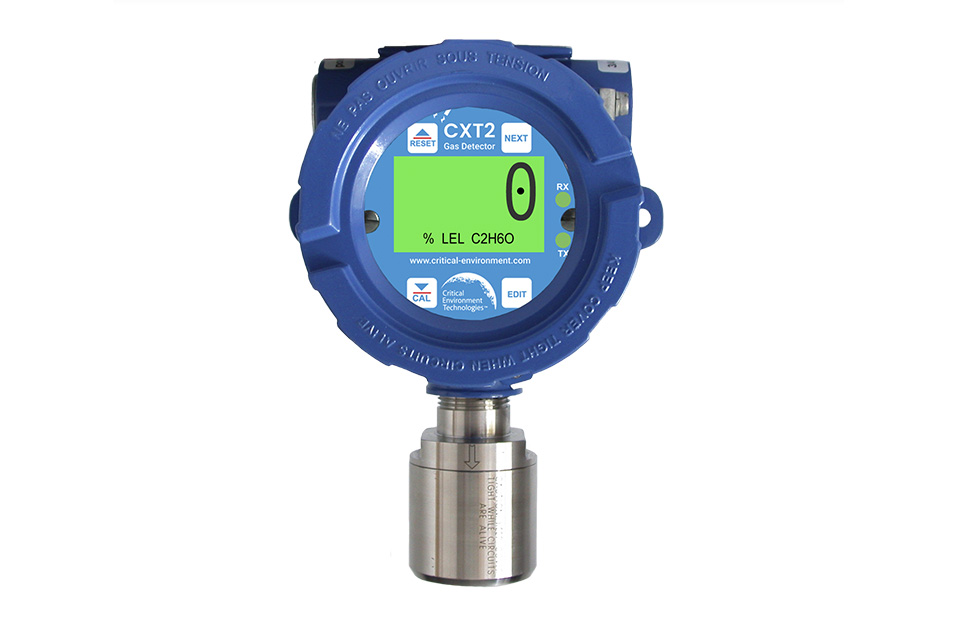
CXT2 Explosion Proof Transmitter
Reliable, accurate monitoring of toxic or combustible gases in potentially explosive and harsh environments, including hazardous-rated areas.
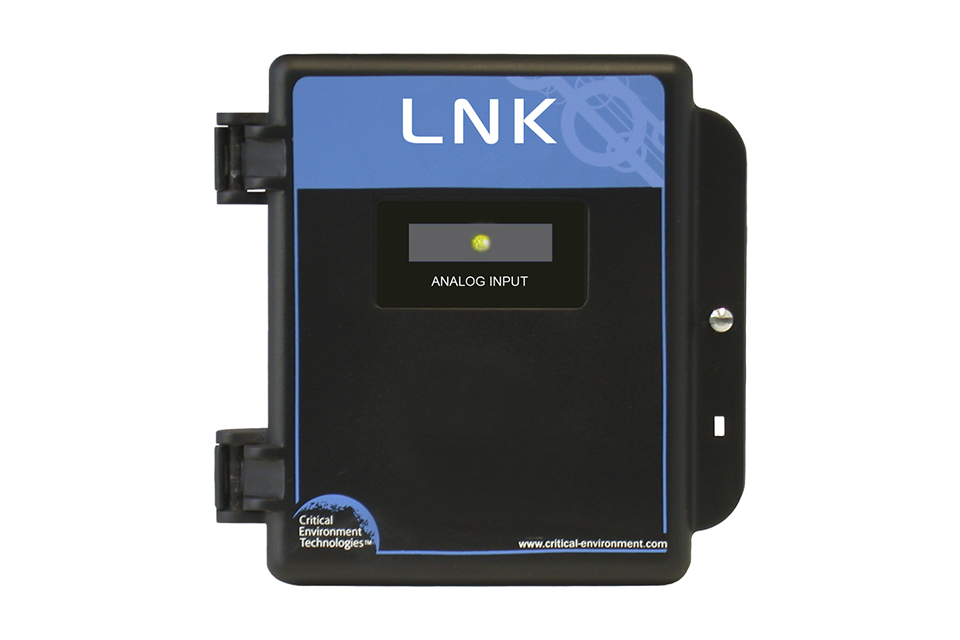
LNK-AI Analog Input Peripheral Device
Adds 4 additional analog inputs to a gas detection system. The LNK-AI Analog Input peripheral device adds four channels of 4 - 20 mA or 0 - 10 volt analog inputs to a Modbus® network configured with one of the FCS Multi Channel System Controllers.
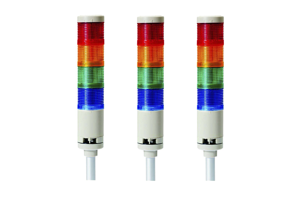
RSL Remote Stack Light
Tower light with modular LED colors with steady or flashing light settings and two different sound types. A compact, pole mounted signal light with flashing or steady modes that are clearly visible from a distance.
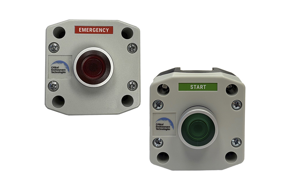
RSW Remote Switch
Enables manual operation of equipment with emergency shutdown, activation or reset as needed. Easy push button action, satisfies compliance as required with some standards.
cGas Detector Ammonia Vent Line Transmitter
For continuous monitoring of Ammonia levels in the vent line of refrigeration systems. Mount indoors on the ammonia vent relief stack in refrigeration systems to help detect equipment failure.
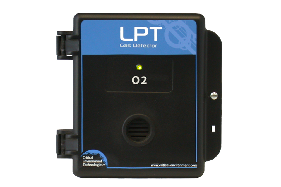
LPT Low Power Transmitter
Single channel, analog gas detector for enclosed parking facilities, recreational facilities, oxygen depletion applications.