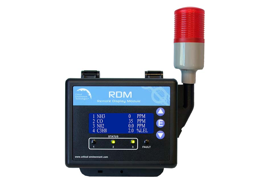
RDM Remote Display
Provides convenient viewing of gas level readings from a secondary location. Displays gas level readings, channel status and faults received from the FCS, offers configurable display settings.
- View gas readings and system statuses in an alternate location
- LCD display and LED indicators
- Internal audible alarm
- Modbus® RS-485 RTU communication
Description
The RDM is a remote display device designed to communicate with the FCS Flexible Control System controllers. It displays gas readings, channel status and faults received from the FCS and can be viewed from a remote, relevant location such as a refrigeration application where there are two different entrances to the chiller room. The RDM employs connection loss detection to ensure the information that is displayed is current. Simple configurations such as adjusting the display contrast and setting the Modbus ID and baud rate can be done in the field. The RDM has several display configurations such as: show/not show one or more channels of interest, readings displayed by line scrolling or page scrolling, display one type of gas and not another, display only the top 4 channels in high alarm, etc. The RDM comes in a standard water / dust tight, corrosion resistant ABS / polycarbonate enclosure with a hinged, secured door.
Available with an optional, factory installed side mounted strobe with audible (Option -L2).
Specifications
Mechanical
| Enclosure | ABS / Polycarbonate, corrosion resistant |
| Weight | 272 g / 9.6 oz |
| Size | 127 x 127 x 71 mm / 5.0 x 5.0 x 2.8 inches |
User Interface
| Display | Backlit, LCD digital display 4-lines x 20-characters |
| Indicator | Status LED indicators for low, mid, high and fault alarms |
| Push Buttons | UP, DOWN and ENTER dome buttons externally mounted for accessing menu options |
Input/Output
| Output | Connection for remote strobe/horn or optional side mounted strobe with audible (Option -L2), 40 mm / 2 in dia, 80 flashes per min, siren volume 85 dB, drip proof |
| Audible Alarm | Internal audible alarm |
| Communication | Modbus® RS-485 RTU |
Electrical
| Power Requirement | CET-RDM: 24 VDC, 0.5 W, Class 2 (24 VDC supplied by the Controller) CET-RDM-L2: 24 VDC, 3 W, Class 2 (24 VDC supplied by the Controller) |
| Wiring | VDC supplied by the Controller, 18 - 22 AWG twisted, shielded, stranded within conduit network wiring (daisy-chain) |
| Fuse(s) | Thermal, resetting |
Environmental
| Operating Temperature | -20°C to 40°C (-4°F to 104°F) |
| Operating Humidity | 15 - 90% RH non-condensing |
Certifications
| Conforms to: | CSA-C22.2 No. 205-12, UL508 (Edition 17):2007 EMC Directive 2004/108/EC, EN 50270:2006, Type 1, EN61010 FCC. This device complies with part 15 of the FCC Rules. Operation is subject to the following two conditions: (1) This device may not cause harmful interference, and (2) this device must accept any interference received, including interference that may cause undesired operation. RoHS compliant circuit boards |
Applications
Detected Gases
Configure Your RDM Remote Display
Select options below to filter configurations.4 configurations available
Showing 1–4 of 4 configurations
CET-RDM
Remote Display
QCC-RDM-L2
Remote Display for QCC w factory side mt Strobe
CET-RDM-L2
Remote Display w factory side mt Strobe
L2-LENS-B
Blue Lens for ML40-24VDCAC Strobe
Not all configurations are listed here. Contact our sales team to discuss your specific requirements.
Documents
Catalog
PDF • 1.1 MB • Brochures
RDM Datasheet
PDF • 442 KB • Datasheets
RDM Operation Manual
PDF • 970 KB • Manuals
Wiring Diagram: FCS-B with Option -AIAO and RDM
PDF • 298 KB • Wiring Diagrams
Wiring Diagram: FCS-M with RDM
PDF • 286 KB • Wiring Diagrams