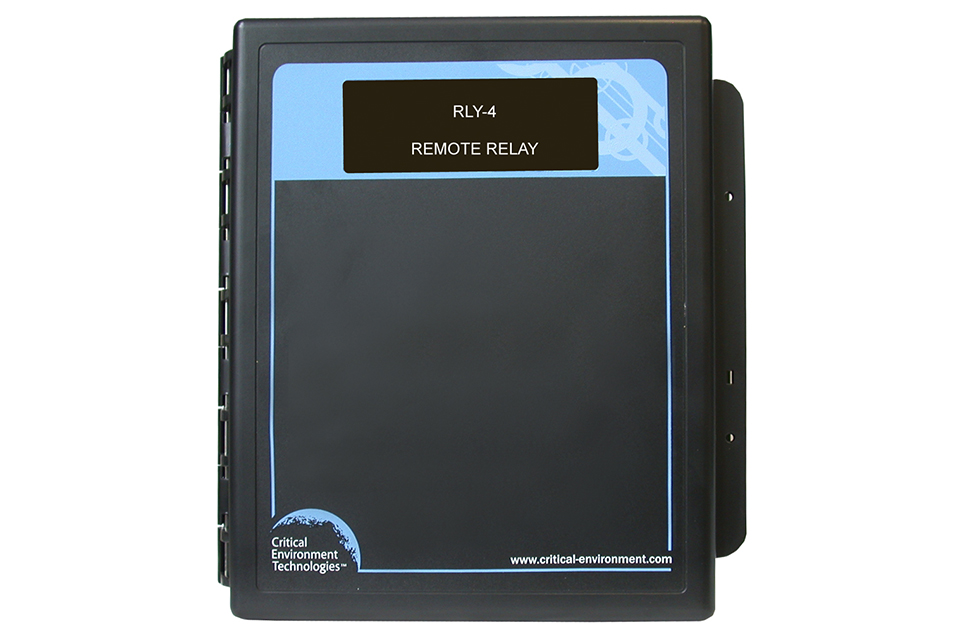
RLY-4 and RLY-8 Remote Relays
Provides an additional 4 or 8 physical relays to a fixed gas detection system plus an additional 2 or 4 horn/strobe drives.
- Increases the number of available relays
- Includes 2 (RLY-4) or 4 (RLY-8) horn/strobe drive outputs
- User selectable gas alarm activation level for each relay (set at the controller)
- User selectable "Failsafe" and latching operation (set at the controller)
Description
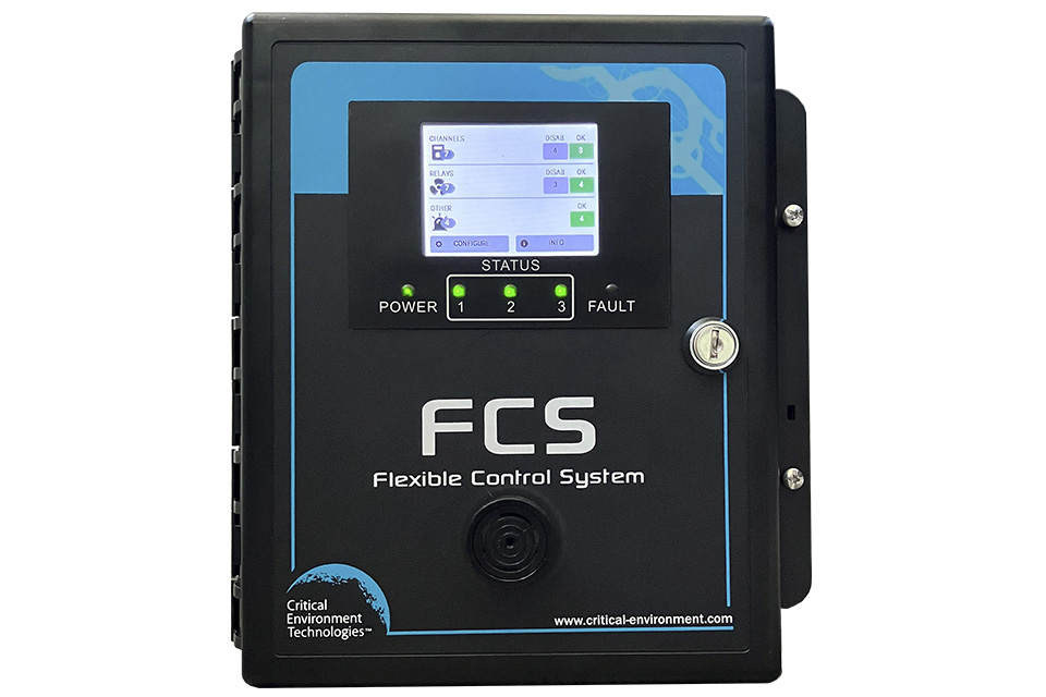
The RLY-4 is designed to communicate with the FCS Multi Channel System Controllers via Modbus® communications protocol. It offers 4 physical relays rated 5 amps @ 240 VAC and 2 horn/strobe drives rated 0.5 amp @ 24 VDC. Similarly, the RLY-4 offers 8 physical relays and 4 horn/strobe drives.
The RLY-4 and RLY-8 can be used to control remote alarms, strobes, exhaust fan starters, make up air fan contactors, etc. In the event that the connection is lost between the controller and the remote relay, a user configurable default state can be set to ensure the relays continue to operate as required. Both devices come in a standard water / dust tight, corrosion resistant ABS / polycarbonate enclosure with a hinged, secured door.
Specifications
Mechanical
| Enclosure | ABS / Polycarbonate |
| Weight | RLY-4: 1.08 kg / 2.4 lbs RLY-8: 1.24 kg / 2.75 lbs |
| Size | 254 x 218 x 109 mm / 10.0 x 8.6 x 4.3 in |
Input/Output
| Relay | RLY-4: 4 SPDT relays rated 5 amps @ 240 VAC, RLY-8: 8 SPDT relays rated 5 amps @ 240 VAC |
| Horn/Strobe | RLY-4: 2 horn/strobe drives 0.5 A @ 24 VDC, RLY-8: 4 horn/strobe drives 0.5 A @ 24 VDC |
| Communication | Modbus® RS-485 RTU |
Electrical
| Power Requirement | 24 VDC, 3W, Class 2 (24 VDC supplied by the Controller) |
| Power Consumption | RLY-4: 3 watts RLY-8: 6 watts |
| Wiring | VDC supplied by the Controller 4-conductor 18 - 22 AWG twisted, shielded, stranded within conduit network wiring (daisy-chain) |
| Fuses | Thermal, resetting |
Environmental
| Operating Temperature | -20°C to 40°C (-4°F to 104°F) |
| Operating Humidity | 15 - 90% RH non-condensing |
Certifications
| Conforms to: | CSA-C22.2 No. 205-12, UL508 (Edition 17):2007 EMC Directive 2004/108/EC, EN 50270:2006, Type 1, EN61010 FCC. This device complies with part 15 of the FCC Rules. Operation is subject to the following two conditions: (1) This device may not cause harmful interference, and (2) this device must accept any interference received, including interference that may cause undesired operation. RoHS compliant circuit boards |
Configure Your RLY-4 and RLY-8 Remote Relays
Select options below to filter configurations.2 configurations available
Showing 1–2 of 2 configurations
RLY-4
Remote Relay w/4 relays for QCC-M,QCC-B, FCS-M & FCS-B
RLY-8
Remote Relay w/8 relays for FCS-M & FCS-B
Not all configurations are listed here. Contact our sales team to discuss your specific requirements.
Documents
RLY-4 and RLY-8 Datasheet
PDF • 314 KB • Datasheets
RLY-4 Operation Manual
PDF • 572 KB • Manuals
RLY-8 Operation Manual
PDF • 556 KB • Manuals
Wiring Diagram: FCS-B with Option AIAO and Remote Relay RLY-4
PDF • 489 KB • Wiring Diagrams
Wiring Diagram: FCS-M with CGAS-D and RLY-4
PDF • 487 KB • Wiring Diagrams
Wiring Diagram: FCS-M with RLY-8 connected to RSH-24V and exhaust fan
PDF • 235 KB • Wiring Diagrams