What are CET's Digital Devices’ Communication Protocols?
Modern gas detection systems support various communication protocols for integration with building automation and control systems. Understanding these options helps optimize system design.
Modern gas detection systems support various communication protocols for integration with building automation and control systems. Understanding these options helps optimize system design.
In order for a digital network to operate successfully, all the devices on the same network must “talk” the same language. The two languages, called communication protocols, used by CETCI’s digital devices are the standard Modbus® RTU RS-485 and BACnet® MS/TP. This document explains how CETCI’s digital devices use both of these communication protocols.
COMMUNICATIONS PROTOCOL TYPE BY PRODUCT NAME
| CETCI’s Digital Devices | Communications Protocol | ||
|---|---|---|---|
| LAN Modbus® RS-485 | WAN Modbus® RS-485 | WAN BACnet® MS/TP | |
| FCS-M Multi Channel Controller | • | • | |
| FCS-B Multi Channel Controller | • | • | |
| FCS-8-M Eight Channel Controller | • | • | |
| FCS-8-B Eight Channel Controller | • | • | |
| QCC-M Quad Channel Controller | • | • | |
| QCC-B Quad Channel Controller | • | • | |
| LPT-M Transmitter | • | • | |
| LPT-P Transmitter | • | • | |
| LPT-B Transmitter | • | ||
| LNK-AO Peripheral Device | • | n/a | n/a |
| LNK-AI Peripheral Device | • | n/a | n/a |
| LNK-XT Peripheral Device | • | n/a | n/a |
| QCC-RDM Remote Device | • | n/a | n/a |
| RLY-4 / RLY-8 Remote Device | • | n/a | n/a |
CETCI DIGITAL TRANSMITTERS CONNECTED TO A CETCI CONTROLLER
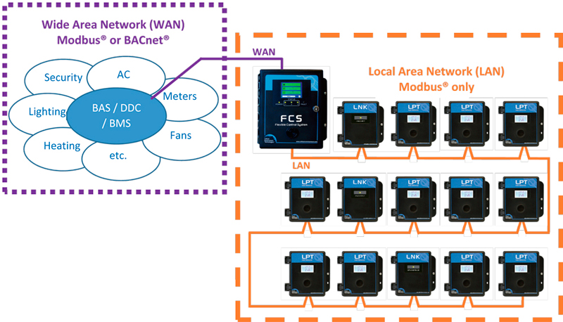
Whether the controller is an FCS or a QCC, the communication protocol used between CETCI’s controllers and digital transmitters is Modbus®. When peripheral devices are required, such as a network extender, additional analog inputs/outputs and remote displays, they too use the Modbus® communications protocol. All of these devices are on the same network, which we refer to as the Local Area Network (LAN) and they always use Modbus® to “talk” the same language.
CONNECTING A CETCI CONTROLLER TO A BAS, BMS, DDC OR OTHER CONTROL PANEL
If the application requires the FCS or QCC to connect to a centralized system such as a Building Automation System (BAS), a Building Management System (BMS), a Direct Digital Control (DDC) system or some other type of control panel, ordering the correct model number of the controller becomes important. The QCC-B, FCS-B and FCS-8-B are configured to output BACnet®. The QCC-M, FCS-M and FCS-8-M are configured to output Modbus®. Whichever communications protocol the centralized system uses, the controller must use. We refer to the centralized system and all the devices it is connected to as the Wide Area Network (WAN).

CONNECTING CETCI DIGITAL TRANSMITTERS DIRECTLY TO A BAS, BMS, DDC OR OTHER CONTROL PANEL
When the application does not require an FCS or QCC, but requires transmitters connected directly to the centralized system, the communications protocol of the centralized system determines which transmitters to order. If the centralized system uses Modbus®, either the LPT-P or LPT-M may be used. If the centralized system uses BACnet®, the LPT-B must be used.
Differences Between the LPT-P, LPT-M and LPT-B
| Features | LPT-P | LPT-M | LPT-B |
|---|---|---|---|
| Up to 3 channels | • | • | • |
| Internal and/or remote sensors configurations | • | • | • |
| Modbus® RTU RS=485 output | • | • | |
| BACnet® MS/TP output | • | ||
| LCD display | • | • | • |
| Internal audible alarm | • | • | |
| Internal relay | • | • | |
| Standard water/dust tight, corrosion resistant enclosure (drip proof) | • | • | • |
| RoHS compliant circuit board | • | • | • |
| Thermal resetting fuse | • | • | • |
| Optional display heater for cold temperature environments | • | • | • |
| Optional splash guard, enclosure is IP54 rated when factory installed | • | • | • |
SUMMARY
In a CETCI digital network, the communications protocol used in the LAN is always Modbus®. The communications protocol used in the WAN is determined by the centralized system and can be Modbus® or BACnet®. When that is known, the appropriate CETCI Modbus® or BACnet® device can be ordered.
Whichever communications protocol is used, to ensure robust data communications, a daisy chain wiring configuration must be used when connecting the devices. This means, four wires run from one end of the network to the other, through the same connections along the entire run. From one digital device to the next digital device, A goes to A; B goes to B; GND goes to GND; 24V goes to 24V.
For additional technical assistance or questions about gas detection applications, contact our application engineering team at help@cetci.com or call 1-888-966-9111.