May 7, 2018
What are CET's Digital Devices’ Communication Protocols?
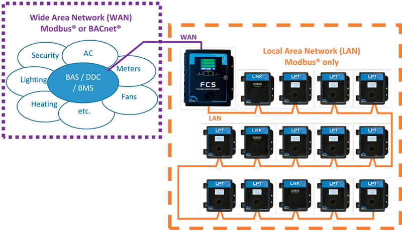
Modern gas detection systems support various communication protocols for integration with building automation and control systems. Understanding these options helps optimize system design.